����ԭʼ����������ʱ���Ӣ��ˮƽ��ϵ������û���ü�����
������Ķ����ѣ���Ҫ���İ汾��������
�����ڶ�Ļ������ǽ�����ר�ҵ��η��빤����
DIY Tube Microphone

��
The G7 (Gic) microphone is designed in the proud European tradition of tube microphones. The spources of inspiration were the Neumann U67 and U47, two legendary microphones that I was lucky enough to have around for reference and comparison when I did this project.
Here's a selection of schematics, showing my inspiration sources - classic broadcast and studio microphones - they are all German designs dating from 1940 to 1960.
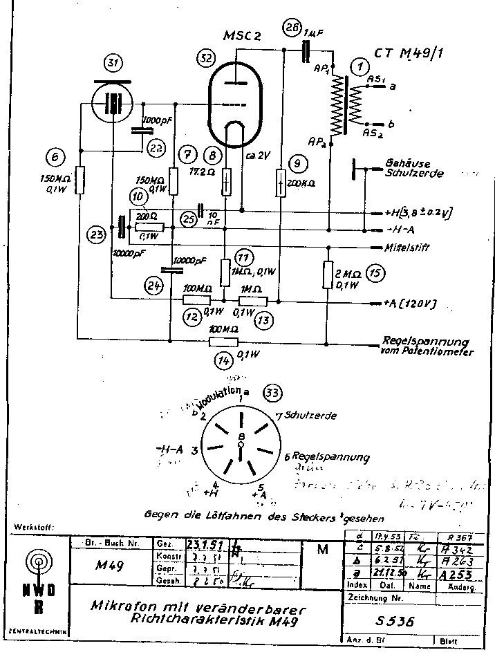
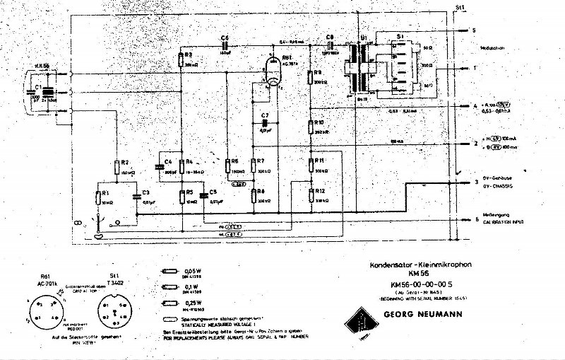
As you can see, my design is somewhat like a combination of the circuits in M49 and U47, but mounted with the tube used in U67. There's really not a lot of complicated electronics here.
The Gyraf G7 Microphone
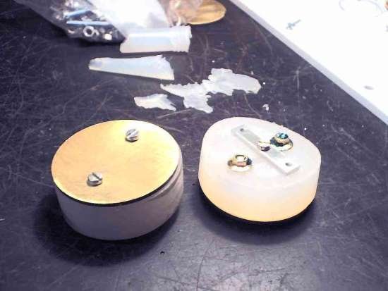
This is a true variable-pattern microphone, capable of doing omni, cardiod and figure-of-eight. This is acheived by polarizing the front and back diagphram of the capsule in different ways with respect to the center electrode.
To act like a microphone, we need a voltage charge across the capsule. When the capsule changes capacitance (that is: the distance between the electrodes are changed by sound pressure) is changed, so does the amount of energy that can be held stored in this capacitor. But as we are charging/discharging with a hell of a small current - the 1GigaOhm resistor - the current really has nowhere to go, and so results in a varying voltage potential across the capsule.
The polarization scheme can be a little difficult to understand at first. To acheive simple remote switching of the polar patterns, a single variable voltage is used for this, only changing the charge of the back part of the capsule.
We want to keep the front electrode of the capsule at ground potential - 0V - at all times, both to act as a shield for incoming electrical disturbance and to avoid electrostatically attracting too much dust from the environment. So to keep a voltage charge across the capsule, we bias the center electrode by the means of two 470K resistors dividing our 160V supply voltage in half - resulting in +80V.
Now we have -80 volts at the front electrode, referred to the center electrode. If we now bias the back electrode with the same (-80V ref. Center = 0V polarization voltage), a positive sound pressure on the back capsule will have the same voltage-potential effect on the center as when applied on the front capsule. This sensitivity pattern is then OMNI directional.
If we polarize the back electrode at +80 Volts, no voltage difference will exist between this and the center electrode, already offset at +80V. This in effect mutes the back capsule, resulting in the CARDIOD directionality.
At last, if we polarize the back capsule at +160 Volts, we'll have a charge of +80 Volts relative to the center electrode. Now a positive sound pressure applied to the back electrode will produce an 180 degrees out-of-phase signal compared to the front capsule. When applying a sound pressure from the side of the microphone, so both capsules sees the same sound pressure, the signals coming from the two capsules will be in opposite phases, effectively canceling each other. This is the FIGURE-OF-EIGHT directionality.
The changing voltage potential on the center electrode of the capsule is picked up and amplified by the EF86 Pentode, which is wired in triode mode - just like the VF14 pentode in the U47. It's input resistance has to be kept VERY high not to disturb the charge/discharge of the capsule, so we use a 1G resistor to bias the grid to 0VDC.
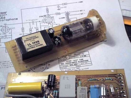
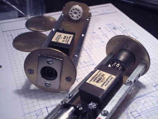
From the anode of the EF86 we take the signal thru' a 2u2 DC blocking capacitor to the output transformer, a Lundahl LL1538 microphone input transformer, here used the "wrong" way around, converting the 15K output impedance of the tube into more useable 600R, and so driving the cable and your microphone preamp with low impedance.
On the PCB board there's an option for adding a trimmer and a capacitor in order to introduce cathode feedback to the tube amplifier stage. This lowers both distortion figures and output impedance, but cancels out a lot of the "tubey" sound - the reason we bother to make a tube microphone in the first place. The reason I have'nt removed this option, is for purely educational reasons - if you want to do some experimenting yourself. This is also where you can put in various equalizations if you like that. But for the best sound - at least to me - leave the tube undisturbed by feedback and other dirty tricks.
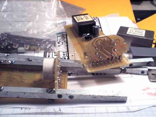
The PCB Layout
The pcb layout for the G7 Mic.
This is an about 420Kbyte PDF file - rightclick and select "save as". The tracks side of the pcb is drawn MIRROR'ED to make closest contact between print and pcb. Think about this when doing the pcb's. When the text on the board reads the right way around seen from tracks side, then you're on right track. Note that a lot of the components mounts on the track side of the board, only the transformer and the angled tube socket goes on the "right" side. This is done in order to minimize total diameter of the assembley, fitting in smaller microphone body tubes.
The power supply
This is a very simple power supply. You only need a couple of mA at 160V for the anode, and about 200mA at 6.3V for the heater. The PSU is based on standard transformers to make it easier for you get hold on them. First there's a mains-to-9V about 5VA transformer, that is rectified and regulated to 6.3V DC by a LM317T regulator. This is sent to pin 6(+) and 7(0) on the XLR, to power the heater in the microphone.
The 9VAC from the first transformer is also taken to the secondary("the wrong way around") of a 220:15V transformer. Now we have about 135V AC on the primary of this second transformer. We rectify this and remove ripple with a 220uF/200V (or maybe larger)electrolytic. We take this DC thru another ripple filter consisting of a 10K resistor and another 220uF/200V (or maybe larger)electrolytic. Now we have our 160VDC for the anode (HT) voltage of our EF86 tube, and run this to pin 2 on the XLR, the ground goes to pin 1.
Now we need the polarizing voltages: 0V, 80V and 160V. The 0 and the 160 are easy, we have them already from the HT supply. We do the 80V simply by dividing the 160V by two 100K resistors, that will also work as "bleeders" ensuring that when you power off the mic, it should be safe to open after 10 to 15 minutes.
BUT ALWAYS CHECK YOUR VOLTAGES BEFORE TOUCHING ANYWAY!!!
Burnt out bleeders often results in burned out tecnicians. And we dont want that! OK - the three different polarization voltages are taken to a 3-pole switch that selects the pattern you want, and goes to XLR pin 5.
The pcb layout for the power supply.
This is an about 220Kbyte PDF file - rightclick and select "save as". This is the PCB for the power supply for the microphone. Made mostly because Steve Cole asked me. Maybe his notes on building the mic will appear here in the future? The power supply connects to the mic by a 7-pin XLR cable, and has the normal 3-pin XLR that carries the output from the mic.
Gerber files of the PCB's:
The Gerber files for the G7 Mic. (41kb .zip file)
The Gerber files for the G7 PSU. (32kb .zip file)
Thanks to Mikkel C. Simonsen for the conversion!
Mechanics:
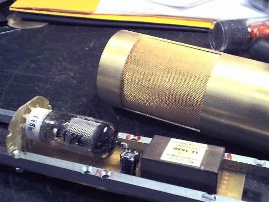
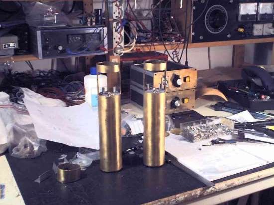
I have'nt made up mechanical drawings for the microphone yet, and maybe it's really not necessary. The microphone body is a 240mm long, 50mm diameter brass tube with a 50 mm cut-out for the capsule and a bottom plate to close it. In this bottom plate, where the 7-pin XLR-connector also mounts, two 5x5mm metal rods are mounted, holding the PCB and protruding all the way to the silicone rubber holding the capsule. The grille protecting the capsule is formed wire mesh made of brass or steel, and glued in place with epoxy. To get the top part of the mesh (the end of the microphone) in right shape, you take a rounded piece of wood, slightly smaller than the inside diameter of the mic body tube, and hammer the mesh gently into shape.
Tim Campbell's microphone building page - 1
Tim Campbell's microphone building page - 2

| Components List: Microphone: 1 pcs. Large-diagphram capsule, e.g. AKG CK12 (from AKG414) 1 pcs. EF86 Audio Pentode 1 pcs. Noval pcb socket (for EF86) 1 pcs. Lundahl LL1538 5:1+1 Microphone input transformer. 2 pcs. 1G (yes, one GigaOhm, 1.000.000.000 Ohms) resistor - RS Components 1 pcs. 33M resistor 2 pcs. 470K resistors 1 pcs. 100K resistor 2 pcs. 10K resistors 1 pcs. 1K6 resistor 1 pcs. 220R resistor 1 pcs. 100u/35V Highgrade Eletrolytic capacitor 2 pcs. 2u2/160V Polyester capacitors 1 pcs. 1u/63V Polyester capacitors 2 pcs. 100nF/160V Polyester capacitor 1 pcs. 10nF/160V Styroflex capacitor 1 pcs. 1nF/160V Styroflex capacitor 1 pcs. 7-pole XLR connector, Male, Chassis mount And the other stuff: PCB Microphone body Harden'ed silicone glue for capsule shockmount Wire mesh for the grille Thin wire for mounting Psu: (220V Model) 1 pcs. Transformer 220:9V, ~5VA 1 pcs. Transformer 220:15V, ~3VA (110V Model) 1 pcs. Transformer 110:9V, ~5VA 1 pcs. Transformer 220:15V, ~3VA 1 pcs. IC-Regulator, LM317. 2 pcs. Bridge Rectifiers, 250V/1A 2 pcs. Electrolytic capacitors, 470uF/200V 1 pcs. Electrolytic capacitor, 2200uF/25V 1 pcs. Electrolytic capacitor, 10uF/35V 1 pcs. Resistor, 1K8 1/4W OR Trimmer, 4K7 1 pcs. Resistor, 470R 1/4W 1 pcs. Resistor, 10K Ohm, 1W 2 pcs. Resistors, 100K Ohm, �W 1 pcs. Metal box for the PSU 1 pcs. 7-pole XLR connector, Female, Chassis mount 1 pcs. 3-pole XLR connector, Male, Chassis mount (for output) 1 pcs. Rotary switch, 1 pole/3way (polar pattern select) 1 pcs. IEC Fused power inlet + T315mA fuse 1 pcs. Mains Power switch 1 pcs. Mains Power indicator light (optional) Cable: 1 pcs. XLR, 7pole, Male, Cable. 1 pcs. XLR, 7pole, Female, Cable. 5M Cable, 7 or 8 conductors, shielded. Native Tube microphone cable is available from e.g. Mogami. Expensive, but good. |
Second opinions:
NEW: Stewart (Zebra50) has set up an illustrative webpage about his attempt this project. Including very nice pics, and - soon - also sound clipshttp://www.omnipressor.com/Other/G7mics/Z-mic1.html
If you like this type of DIY-projects, you should also check out Kev Ross's DIY-Page on Recording.org:
The GroupDIY forum would be a good place to ask questions about this project:
http://www.groupdiy.com/
...there's a good chance you will find me hanging around there...Michael Krusch's version of this mic, based on a scrap Rode NT2 and OEP transformer:
http://www.digital-synthologie.de/rode_nt2/index.html
If problems arises, errata and changes will be posted on this page.
Jakob Erland
22-10-2003
REVISION HISTORY:
07-07-2002: Pcb Rev# 2, Schematic Rev# 1: Original
20-07-2002: PSU pcb Rev#1. Schematic redrawn. PDF-files for pcb's.
27-01-2003: Components list changed to support the LM317 heater supply.
 ���������� 11011402011520��